
When a clean cut turns rough
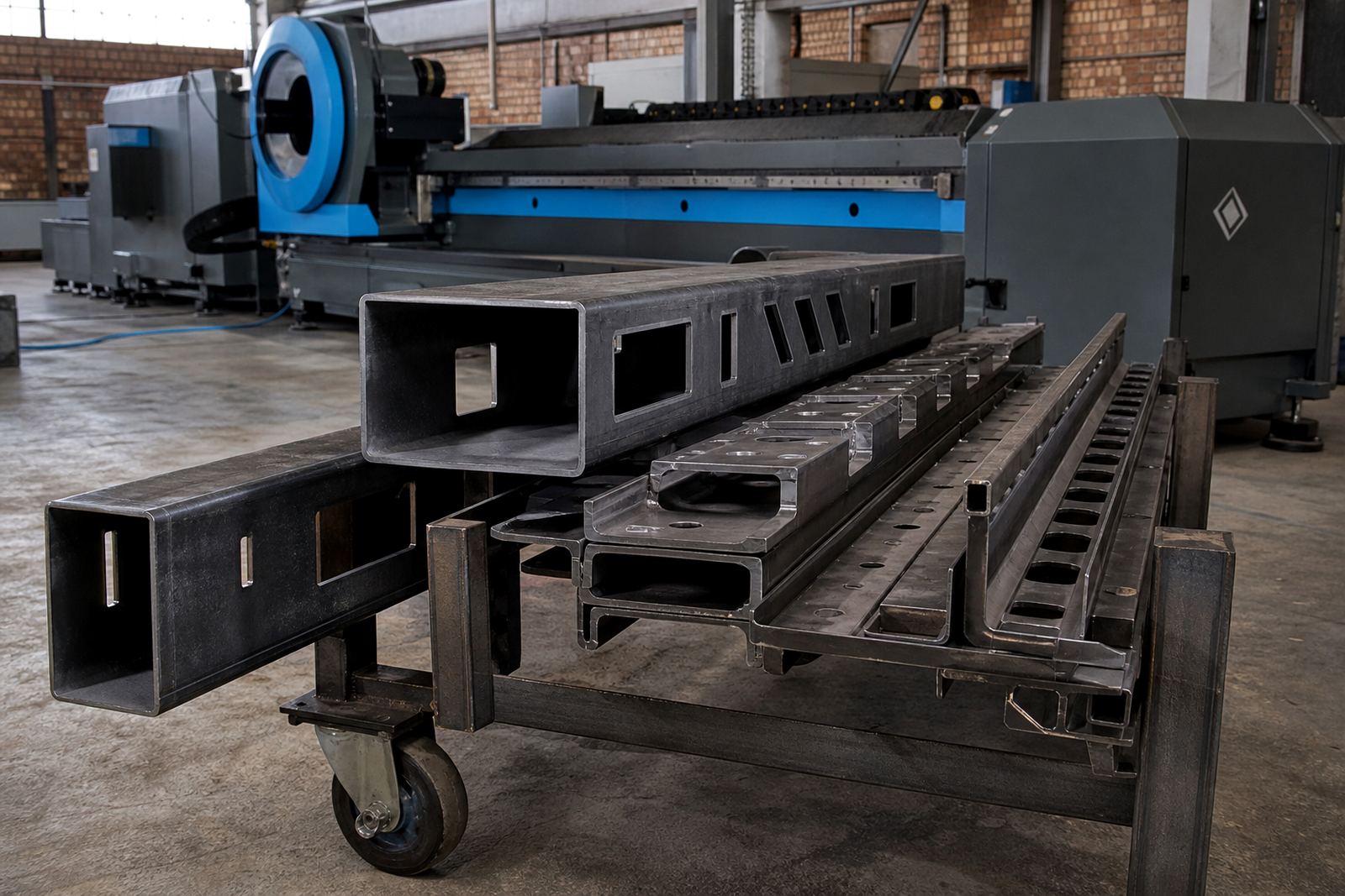
Tube cutting asks more of the machine than flat sheet work. Round, square and rectangular tube can shift under clamp pressure, and angle or channel brings extra edge conditions that change how the beam behaves. When a part leaves the machine with heavy burrs, a jagged edge or a heat mark that runs too far down the face, the problem is usually in the chain of setup rather than one single fault.
A fabricator in Wadeville had repeated drag marks on mild steel tube after a shift change. The first check was not the program, it was the chuck grip, the nozzle height and whether the tube was sitting true across the support bed. Once those were reset and the nesting order was reviewed, the cut path settled and edge quality improved without changing the job itself.
In fibre laser tube cutting, our machine is one factor, but material, setup and gas settings all affect the final result. Material quality, wall thickness, assist gas, lens condition and the chosen lead in all leave their mark on the finished edge.
Rough edges usually start with setup
Rough edges can show up as a light feather, a sandy finish or a hard burr that needs grinding. On thin wall tube, that often points to travel speed being too low, gas pressure not matching the thickness, or focus sitting in the wrong position. On heavier sections, the issue may be a worn nozzle, poor beam centring or a clamp that allows the tube to move during the cut.
- Check that the tube is clamped square and supported along its length.
- Match assist gas type and pressure to the material and thickness.
- Inspect nozzle wear, ceramic condition and lens cleanliness.
- Review cutting speed if the edge looks melted rather than sliced.
- Confirm the cut path is not forcing the head through unnecessary corners.
Even a small setup shift can show up across a full batch. If the first parts look acceptable and later parts lose edge quality, the issue may be heat build-up, dirty consumables or material from a different supplier with a harder scale layer.
Dross is a warning, not a finishing step
Dross at the bottom edge is a sign that molten material is not clearing the kerf properly. On carbon steel tube, that can come from weak gas flow, a nozzle set too high, or a cut speed that leaves the melt hanging on the underside. On stainless, the same symptom may point to gas purity, focus position or a pierce routine that is too aggressive for the wall thickness.
Plenty of shops scrape dross off and carry on, but that only hides the cause. If the kerf is full of re-solidified metal, the job is already telling you something about pressure, nozzle size or torch alignment. In profile cutting, the same issue can appear on channels and angle iron where the corner breaks the gas flow and leaves a heavy lip.
When dross keeps appearing in the same place on every part, inspect the nesting pattern. Parts packed too close together can trap heat and change how the plume clears. A more open nest may use more tube, but it can leave a cleaner edge and save finishing time.
Poor pierce starts need a different eye
Bad pierce starts often look like a crater, a blown top edge or a hole that opens off centre. That is more common on coated tube, oily stock or material with mill scale that has not been cleaned well enough for the job. If the pierce is too fast, the blowback can mark the tube wall and weaken the first section of the cut.
For tube work, the pierce must suit the diameter and wall thickness as much as the metal grade. A programme that works on light square tube may give trouble on larger round sections, especially where the pierce lands near a seam or a welded join. Bevel heads can add another layer here, because the cutting angle changes how the melt breaks away.
- Set the pierce height for the actual material, not a similar job.
- Use a pierce delay that gives the kerf time to open cleanly.
- Keep the head clear of scale, oil and splash marks.
- Move pierce points away from seams where the layout allows it.
Chucks, support and tube movement
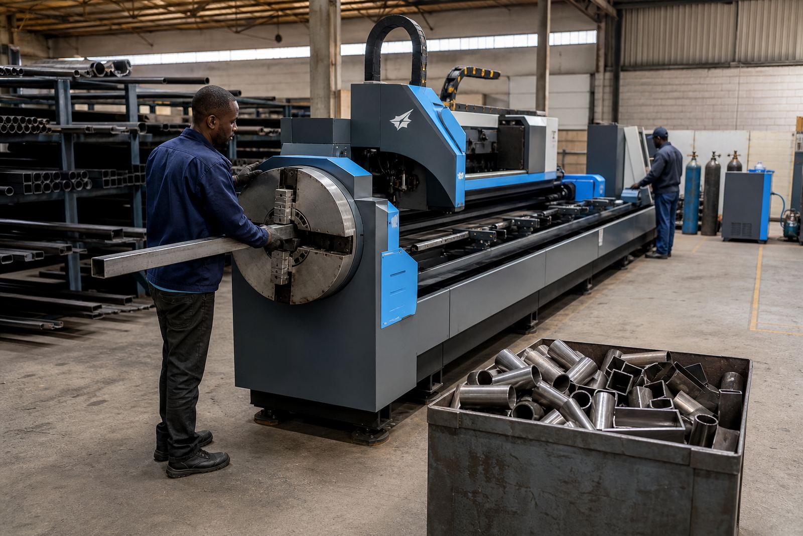
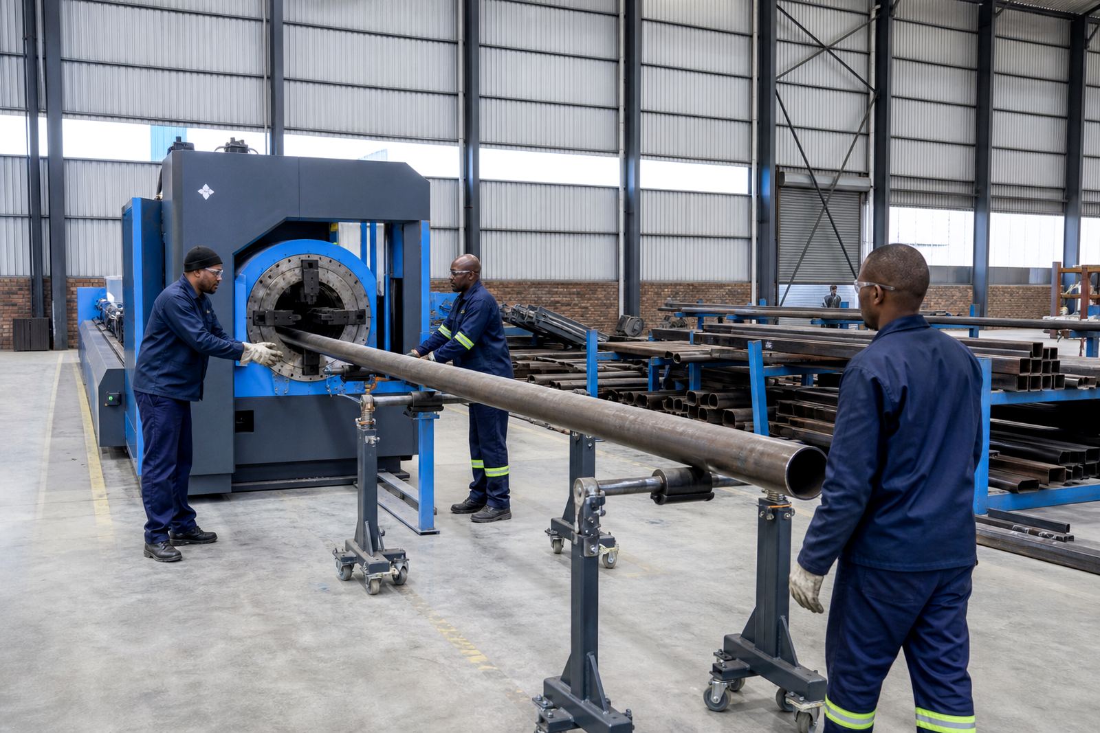
On a fibre laser tube machine, the chuck system is part of cut quality. If the tube slips, twists or sits under uneven grip, the cut path shifts and the result shows up as taper, poor hole position or an edge that looks fine at one end and poor at the other. That matters on long stock where the tube passes through several support points before the cut is complete.
Chuck alignment is often overlooked because it does not make noise until parts start failing. Sibusiso Bhengu, who leads installations, checks how the tube feeds, how the supports carry weight and how the clamping force changes from one diameter to the next. That is where a lot of hidden variation lives, especially on mixed batches of round tube, rectangular sections and channel.
When the machine is cutting angle or open section, the contact points are fewer and the part can vibrate if the support spacing is wrong. That vibration often shows up as ripple on the edge or a slight step where the beam enters and exits the profile.
Assist gas and nesting shape the finish
Assist gas is not there just to blow debris away. It controls edge oxidation, helps eject molten metal and affects how much post work the part needs. Oxygen, nitrogen and compressed air each behave differently, and the wrong choice for a job can give rough edges or heat tint that is hard to remove later. Gas setup also needs the right pressure and clean delivery path, otherwise the cut can suffer from poor clearing at the nozzle.
Nesting software matters too. A clever layout can shorten cycle time, but it still has to respect lead ins, pierce points and the way heat moves through a tube bundle. Ayanda Mashaba works on application checks where the programme looks neat on screen but the real machine shows overlap, distortion or avoidable scrap. That kind of adjustment usually saves more than a small gain in cutting speed.
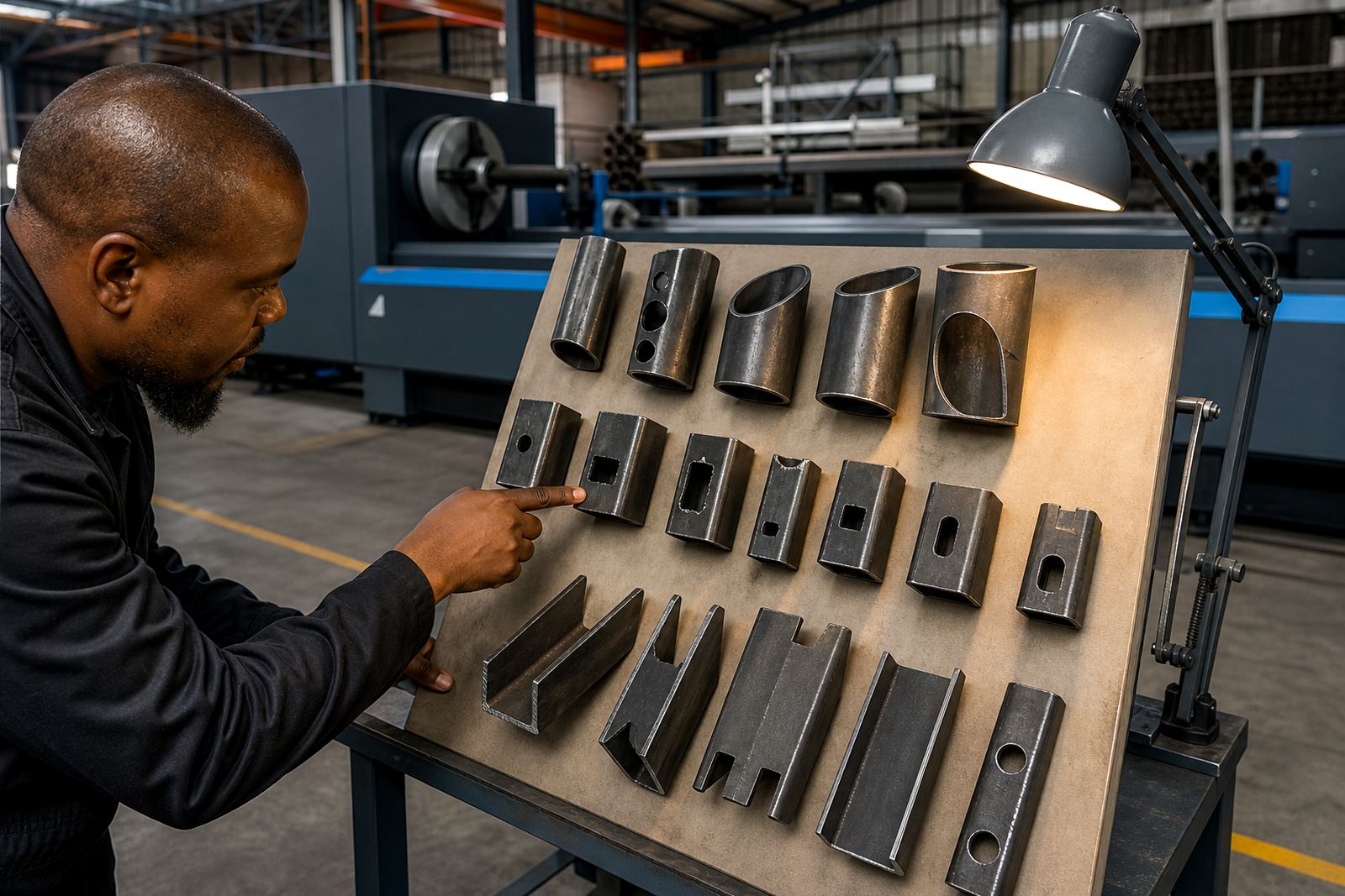
Where the job includes repeated holes, slots and mitres, it helps to run a test piece before committing to a long batch. The test shows whether the gas, focus and feed rate suit the actual stock, not the drawing alone.
A cleaner cut starts with a tighter routine
A small number of common causes usually sit behind repeat cutting defects. The useful habit is to check the machine in the same order each time, so the cause is found before the material gets wasted. Leanne Mabuza often pushes operators to note the symptom first, then the likely source, then the correction. That record makes the next problem easier to isolate.
- Watch the edge finish on the first part, not the tenth.
- Separate pierce faults from cut faults in your notes.
- Inspect consumables before blaming the programme.
- Keep material batches apart when thickness or finish changes.
- Use preventive maintenance to protect alignment, gas flow and motion accuracy.
For fabricators in Germiston, Pretoria, Durban, Cape Town and Gqeberha, the same defect can have a slightly different cause depending on humidity, material supply and how the workshop handles stock. The common thread is that rough edges, dross and poor pierce starts are useful clues. Read them early, and the machine spends more time cutting and less time sending parts to rework.